
Contents
Stationary battery testing........................... 4
Why perform impedance testing?...................................... 4
Why perform discharge testing?......................................... 5
Why backup batteriesare needed................. 6
Whytest battery systems.................................................... 6
Why batteries fail.................................................................. 6
Battery types........................................... 7
Lead-acid overview................................................................. 7
Nickel-Cadmium Overview.................................................. 7
Battery construction and nomenclature................... 8
Configurations...................................................................... 8
Single post batteries......................................................... 8
Multiple post batteries..................................................... 8
Failure modes.......................................... 9
Lead-acid (flooded) failure modes...................................... 9
Lead-acid (VRLA) failure modes............................................ 9
Nickel-Cadmium failure modes........................................ 10
Maintenance philosophies.......................... 11
Howto maintain thebattery................................ 11
Standards and common practices.................................... 11
IEEE 450........................................................................... 11
Inspections.................................................................. 11
Capacity test (discharge test) should be done......... 11
IEEE 1188......................................................................... 12
Inspections.................................................................. 12
Capacity test (capacity test) should be done............ 12
Battery replacement criteria....................................... 12
IEEE 1106......................................................................... 12
Inspections.................................................................. 12
Capacity test (discharge test) should be done......... 12
Summary of best way to test and evaluate
your battery......................................................................... 12
Test intervals................................................................... 12
Practical battery testing............................. 13
Capacity test...................................................... 13
Battery testingmatrix – IEEE recommended practices 13
of vented lead acid battery............................................... 14
Impedance test................................................... 15
Impedance theory.............................................................. 15
Intercell connection resistance...................................... 16
Testing and electrical paths............................................ 17
Voltage............................................................................ 17
Specific gravity................................................................ 17
Float current.................................................................... 18
Ripple current.................................................................... 18
Temperature................................................................... 18
Data analysis..................................................... 19
Locatingground faults on DC systems without sectionalizing 22
Overview......................................................................... 22
Current test methods..................................................... 22
A better test method...................................................... 22
Frequently asked questions........................ 23
Battery technology summary..................................... 23
Megger products overview......................... 24
Impedance test equipment................................... 24
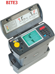
BITE®3............................................................................. 24
BITE®2 and BITE®2P.......................................................... 24
BITE® accessories.................................................................. 25
BITE®3 Accessories...................................................... 25
BITE®2 and BITE®2PAccessories................................... 25
TORKEL 860..................................................................... 26
BVM................................................................................. 26
TORKEL 900..................................................................... 27
Ground fault tracingequipment............................ 27
Battery Ground Fault Tracer (BGFT)............................. 27
Battery Ground-fault Locator (BGL)............................. 28
Digital Low Resistance Ohmmeters (DLRO®)
and Microhmmeters (MOM)................................. 28
DLRO200 and DLRO600................................................... 28
DLRO 247000 series........................................................ 28
DLRO10 and DLRO10X..................................................... 29
MJÖLNER 200 and MJÖLNER600.................................. 29
MOM200A and MOM600A........................................... 29
MOM690......................................................................... 29
Insulation ResistanceTest Equipment....................... 30
MIT400/2 series insulation resistance testers............... 30
Acceptance & Maintenance Test Data
ManagementSoftware..................................................... 31
Test forms.................................................................... 31
![]()
3
STATIONARY BATTERY TESTING
The stationary backup batteries arethe life line inany critical system, a life line that simply cannot fail. In order to ensure continuous operation, it isrecommended to implement a sound and solid battery maintenance program.
Each of the various standards (IEEE 450, IEEE 1188, IEEE1106) havetheir own best practices for battery maintenance, which we have summarized into the following:
■ Perform a capacity test when the battery is new as part of theacceptance test.
■ Performan impedance test at the same time to establish baseline values for the battery.
■ Repeat the above within 2 years for warranty purposes.
■ Performan impedance test every year on flooded cells and quarterly on VRLA cells.
■ Perform capacity tests at least forevery 25% ofexpected service life.
■ Perform a capacity test annually when the battery has reached 85%of expectedservice life or if the capacity has dropped more than10% since the previous test or is below 90% of the manufacturer‘srating.
■ Perform a capacity test if the Impedance value has changedsignificantlyfrom the initial baseline value.
■ Follow a given practice(preferably from the IEEE standard) for all temperature, voltage, gravity measurements etc. and create a report.This will be a great help for trending and fault tracing.
This document provides an example of a thorough maintenance program that will ensure high reliability for a stationarybattery string. Some critical locations might
need more attention, and some rural environments less, thecondition of the environment of the batteryand the condition of the battery itself areimportant parameters to set up a suitable and solid maintenance program.
Why performimpedance testing?
Batteries canfail between discharge tests. This quick and easy test willincrease reliability for your critical loads.
Not only will this informyou about chemicalchanges in your batteries but it will also test your inter-cell connections, thebattery charge balance as well as the state of health of thecharger.
The AC impedance measurement hasa distinct advantage over the DC resistivemeasurement.

Batteries are not resistors. They have capacitance due to a double layer effect that occurs whenliquids come in contact with solids (plates and electrolyte). This value changes earlier in the batteryaging process. DC testing ignoresthis parameter.
VLA batteries aretypically large batteries with low impedance. You need adequate current totest these large lowimpedance batteries. Small hand-held testersdo not have the current. The BITE2 testswith a full 10 A of current. More than enough to get reliable repeatable measurements on large floodedcells.
VRLA batteries typicallyfail in what is referredto as an open state. This means currentcannot pass through the cell. For this reason, parallelstrings are recommended in critical systems when using VRLA batteries.
You can getfalse measurements in theparallel path unless you sectionalize the string. The Megger BITE3is the only battery tester designedto measure the escape currenton parallel strings, avoidingthe need to sectionalizing the string.

 1 = 1 + 1
RT R1 R2
1 = 1 + 1
R1 RT R2
www5.megger.co
Why backup batteries are needed
Batteries are used to ensure thatcritical electrical equipment is always on. There are somany places where batteries are used – it is nearly impossible to list them all. Some of the applications for batteries include:
■ Electric generating stations and substations for protection andcontrol ofswitches and relays
■ Telephone systems to support phoneservice, especially emergency services
■ Industrial applications for protection andcontrol
■ Backup of computers, especially financial data and information
■ “Less critical” business informationsystems
Without battery back-uphospitals would have to close theirdoors until power is restored. But even so, there are patientson life supportsystems that requireabsolute 100% electric power. For those patients,as it was once said, “failure is not anoption.”
Just look around to seehow much electricity weuse andthen to see how important batterieshave become in our everyday lives. The many blackoutsaround the world show how criticalelectrical systems have become to sustain our basic needs.
Batteries are used extensively and without them many of the services that we take for granted would fail and cause innumerableproblems.
Why test battery systems
There are three main reasons to test battery systems:
■ Toinsure the supported equipment is adequately backed-up
■ To prevent unexpected failures by tracking thebattery’s health
■ To forewarn/predict death
And, there arethree basic questions that battery users ask:
■ What is the capacity and the condition of the batterynow?
■ When will it need to be replaced?
■ What can be done to improve / not reduceits life?
Batteries arecomplex chemical mechanisms. They have numerous components from grids, active material, posts, jar and cover,etc. – any one of which can fail. As with all
manufacturing processes, no matter how well they aremade, there is still some amount of black art to batteries (andall chemical processes).
A battery is two dissimilar metallic materials in an electrolyte. In fact, you can put a penny and a nickel in half of a grapefruitand you now have a battery. Obviously, an industrial battery
is more sophisticated than agrapefruit battery. Nonetheless, a battery,to work the way it is supposed to work must be maintained properly. A good batterymaintenance program may prevent,or at least, reduce the costs and damage to critical equipment due to an AC mainsoutage.
Even though there are many applications forbatteries, standby batteries are installed for only two reasons:
■ To protect and support critical equipment duringan ACoutage
■ To protect revenue streams due to the loss of service
The following discussion about failure modes focuses on the mechanisms and types of failure and how it is possibleto find weak cells. Below is a section containing a more detaileddiscussion about testingmethods and their pros and cons.
Why batteries fail
In order for us to understand why batteries fail,unfortunately a little bit of chemistry is needed. Thereare 2 main battery chemistries used today in standby applications, lead acid and nickel cadmium.Other chemistries such as lithiumion are prevalenton portable and cyclic applications, but are not ideal fornon-cyclic stationary applications.
Volta invented theprimary (non-rechargeable) battery in1800. Planté invented the lead-acid battery in 1859 and in 1881Faure first pasted lead-acid plates.With refinements over thedecades, it has become a critically important back-up power source.The refinements include improved alloys, grid designs,jar and cover materials and improved jar-to-cover and post seals. Arguably, the most revolutionary development for the lead acid battery was the valve-regulated development. Manysimilar improvements in nickel-cadmium chemistry have been developedover the years.
Battery types
There are several main types ofbattery technologies with subtypes:
■ Lead-acid
■ Flooded (wet): lead-calcium,lead-antimony
■ Valve RegulatedLead-acid, VRLA (sealed): lead-calcium, lead-antimony-selenium
■ Absorbed Glass Matte (AGM)
■ Gel
■ Flat plate
■ Tubular plate
■ Nickel-cadmium
■ Flooded
■ Sealed
■ Pocket plate
■ Flat plate
Lead-acid overview
The basic lead-acid chemical reaction ina sulphuric acid electrolyte, where the sulphate of the acid is part of the reaction, is:
PbO2 + Pb+ 2H2SO4 ![]() 2PbSO4 + 2H2 + 1⁄2O2
2PbSO4 + 2H2 + 1⁄2O2
The acid is depleted upon discharge and regenerated upon recharge. Hydrogen and oxygenform during discharge and float charging (becausefloat charging is counteracting self- discharge). In flooded batteries, they escape and water must be periodically added. In valve-regulated, lead-acid (sealed)batteries, the hydrogenand oxygen gases recombine to form water. Additionally, in VRLA batteries, the acidis immobilized by an absorbedglass matte (AGM) or in a gel. The matte
is much like the fibre-glass insulation used in houses. It traps the hydrogen and oxygen formedduring discharge and allows them to migrateso that they react back to form water.This is why VRLA never needs water added compared to flooded (wet,vented) lead-acid batteries.
A battery has alternating positive and negative platesseparated by micro-porous rubber in flooded lead-acid, absorbed glass matte in VRLA, gelled acid in VRLA gel batteries or plastic sheeting in NiCd. All of the like-polarityplates are welded together and to the appropriate post.
In the case of VRLA cells, some compression ofthe plate- matte-plate sandwichis exerted to maintain good contactbetween them. There is also a self-resealing, pressure reliefvalve (PRV) to vent gases when over-pressurization occurs.
Nickel-Cadmium Overview
Nickel-Cadmium chemistry is similar in some respects to lead-acidin that there are two dissimilar metals in an electrolyte. The basic reaction in a potassiumhydroxide (alkaline) electrolyte is:
2 NiOOH + Cd +2 H2O ![]() Ni(OH)2 + Cd(OH)2
Ni(OH)2 + Cd(OH)2
However, in NiCd batteries the potassium hydroxide (KOH) does not enterthe reaction like sulphuric acid does in lead-acidbatteries. The construction is similar to lead-acid in that there are alternating positive and negative platessubmerged in an electrolyte. Rarely seen, but available, are sealed NiCdbatteries.

7
Battery construction andnomenclature
Now that we know everything there is to know about batterychemistry, except for Tafel curves,ion diffusion, Randles equivalent cells, etc., let’s move on to batteryconstruction. A battery must have several componentsto work properly: a jar to hold everything and a cover, electrolyte (sulphuric acid or potassium hydroxidesolution), negative and positive plates, top connections welding all like-polarity plates together and thenposts that are also connected to the top connections of the like-polarity plates.
All batteries have one more negative plate than positive plate. That is becausethe positive plate is the working plate and if thereisn’t a negative plate on the outsideof the last positive plate, the whole outer side of last positiveplate will not haveanything with which to react and create electricity. Hence, there is always an odd number of plates in a battery, e.g., a100A33 battery is comprised of 33 plates with 16 positive plates and 17 negativeplates. In this example, each positiveplate is rated at 100 Ah. Multiply16 by 100 and the capacityat the 8-hour rate is found, namely,1600 Ah. Europe uses a little different calculation than the USstandards.
In batteries that have higher capacities, there are frequently four or six posts. This is toavoid overheating of the current- carrying components of the batteryduring high currentdraws or lengthy discharges. A lead-acid batteryis a series of plates connected to top lead connected toposts. If the top lead, posts and intercell connectors are not sufficiently large enough
to safely carrythe electrons, then overheating may occur(i2Rheating) and damage the battery or in the worst cases,damage installed electronics due to smoke or fire.
To prevent plates from touchingeach other and shorting the battery,there is a separator between each of the plates. Figure 1 is a diagram of a four-post battery from thetop looking through the cover. It does not show the separators.
Configurations
Batteries come in various configurations themselves. Add to thatthe many ways that they can be arranged, the number of possible configurations is endless. Of course, voltage plays the biggest part in a battery configuration. Batteries have multipleposts for higher currentdraws. The more current needed from a battery,the bigger the connections must be. That includesposts, intercell connectors and buss bars and cables.
Single post batteries
Smaller battery systems are usuallythe simplest battery systems and are the easiestto maintain. They usually have single post batteries connected with solid intercell connectors. Frequently,they are quite accessible but because they are small and can
be installed ina cubby hole occasionally, they maybe quite inaccessible fortesting and maintenance.
Multiple post batteries
Batteries with multiple posts per polarity start tobecome interesting quickly. They are usually larger and frequently are morecritical.
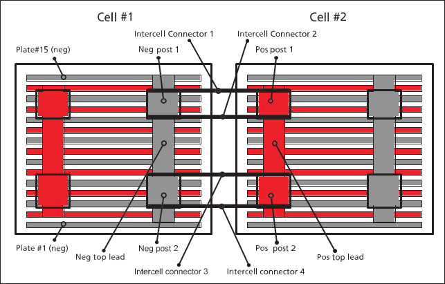
Figure 1 Battery construction diagram
Failure modes
Lead-acid(flooded) failure modes
■ Positive grid corrosion
■ Sediment (shedding) build-up
■ Top lead corrosion
■ Plate sulphation
■ Hard shorts (paste lumps)
Each battery type has many failure modes, some ofwhich are more prevalent than others. Inflooded lead-acid batteries, the predominant failuremodes are listedabove. Some of themmanifest themselves with use such as sedimentbuild-up due to excessive cycling. Others occur naturally such as positive grid growth (oxidation). It isjust a matter of time before the battery fails. Maintenance and environmental conditions can increase or decreasethe risks of premature batteryfailure.
Positive grid corrosion isthe expected failure mode of flooded lead-acid batteries. The grids are lead alloys(lead-calcium, lead-antimony, lead-antimony-selenium) that convert to leadoxide over time. Since the lead oxide is a bigger crystalthan lead metal alloy, the plate grows. The growth rate has been wellcharacterized and is taken into account when designingbatteries. In many battery data sheets, there is a specification
for clearance at the bottom of the jar to allow for plate growth in accordance with its ratedlifetime, for example, 20 years.
By the designed end of life, the plates may have grownsignificantly. If they grow too much, they can pop the top off the battery or crack the jar. Excessivecycling, temperature and over-charging can increase the speed of positive grid corrosion.Impedance will increaseover time corresponding to the increase in electrical resistance of the grids tocarry the current. Impedance will also increaseas capacity decreases as depictedin the graph in figure 2.
Sediment build-up (shedding) is a functionof the amount of cycling a battery endures. This is more often seen in UPS
batteries butcan beseen elsewhere. Shedding isthe sloughing off ofactive material from the plates, converting to white
lead sulphate. Sediment build-up isthe second reason battery manufacturershave space at the bottom of the jars to allow for a certain amount of sedimentbefore it builds-up to the point of shorting across the bottom of the platesrendering the battery useless. The float voltage will drop and the amountof the voltage drop depends upon how hard the short is.
Shedding, inreasonable amounts, is normal.
Some battery designshave wrapped platessuch that the sediment is held against the plateand is not allowed to drop to the bottom. Therefore, sediment does not build-upinwrapped plate designs. The most common application of wrapped platesis UPS batteries.
Corrosion of the top lead, which is the connection between the plates and the posts is hard to detecteven with a visual
inspection since it occurs near the top of the batteryand is hidden by the cover. The battery will surely fail due to the high current draw when the AC mains drop off. The heat build-upwhen discharging will most likely melt then crack open and then the entire stringdrops off-line, resulting in a catastrophic failure.
Sulphation isthe process of converting active plate material to inactive white lead sulphate.Plate sulphation occurs when a battery is discharging.
As the batteryis charged this process reverses. If a charger voltage is set too low or arecharge is incomplete then the platesremain partially sulphated. The longer they remain this way the moredifficult it will be to reverse the process. As the plates sulphate, they lose active material so the internal impedance of the cell increases while the capacity of the celldrops.
Lead-acid (VRLA) failure modes
■ Dry-out (Loss-of-Compression)
■ Plate Sulphation (see above)
■ Soft and Hard Shorts
■ Post leakage
■ Thermal run-away
■ Positive grid corrosion (see above)
Dry-out is a phenomenon that occurs due to excessive heat (lack of properventilation), over charging, which can cause elevated internal temperatures, high ambient(room) temperatures, etc. At elevated internaltemperatures, the sealed cells will vent through the PRV. When sufficient
electrolyte isvented, theglass matte no longer is incontact with the plates, thus increasing the internal impedance and reducingbattery capacity. In some cases, the PRV can beremoved and distilled water added (but only in worst case scenariosand by an authorized service company since
removing thePRV mayvoid thewarranty). This failure mode is easily detected by impedance andis oneof themore common failure modesof VRLA batteries.
Soft (a.k.a. dendriticshorts) and Hard shorts occur for a numberof reasons. Hard shorts are typically causedby paste lumps pushingthrough the matte and shorting out to the adjacent (opposite polarity) plate.Soft shorts, on the other hand, are caused by deep discharges. When the specific gravity of the acid gets too low,the lead will dissolve into it. Since the liquid(and the dissolved lead) are immobilized by the glass matte,when the batteryis recharged, the lead comes out of solution forming threads ofthin lead metal, known as dendrites inside the matte. In some cases, the lead dendritesshort through the matte to the other plate. The float voltage may drop slightlybut impedance can find this failure mode easily but is a decrease in impedance, not the typical increaseas in dry-out. See figure 2, Abnormal Cell.
Thermal run-away occurswhen a battery’s internal componentsmelt-down in a self-sustaining reaction.
Normally, this phenomenon can be predictedby as much as four months orin as little as two weeks. The impedance will increasein advance of thermal run-away as does float current. Thermal run-awayis relatively easy to avoid,simply by using temperature-compensated chargersand properly ventilating the battery room/cabinet. Temperature-compensated chargers reduce the charge currentas the temperature increases.
Remember that heating is a function of the square of thecurrent. Even though thermal run-awaymay be avoided by temperature-compensation chargers, the underlying cause is stillpresent.
Nickel-Cadmium failuremodes
NiCd batteries seem to be more robustthan lead-acid. They aremore expensive to purchase but the cost of ownershipis similar to lead-acid, especially if maintenance costs are usedin the cost equation.Also, the risks of catastrophic failure are considerablylower than for VRLAs.
The failure modes of NiCd are much more limited than lead- acid. Some ofthe more important modes are:
■ Gradual loss of capacity
■ Carbonation
■ Dendrite formation
■ Cycling
■ Iron poisoning ofpositive plates
Gradual loss of capacity occurs from the normal aging process. It is irreversible but is not catastrophic, not unlike grid growthin lead-acid.
Carbonation isgradual andis reversible. Carbonation iscaused by the absorption of carbon dioxide from the air into thepotassium hydroxide electrolyte which is why it is a gradual process. Without proper maintenance, carbonation can cause theload to not be supported, which can be catastrophic to supported equipment. It can be reversed by exchanging the electrolyte.
Dendrites formation occurs naturally in the cadmium of a NiCd battery.Over time, the dendrite will pierce the separator.This leads to micro-shorts thatincrease the self discharge rate of the battery.This appears as a loss in capacityand is often referred to as memory effect or floating effect. Deepcycling the battery can help reversethese effects. The heat created during the recharge processof a deep cycle burns out the dendrites. However, the damageto separator will provide a path for future dendrite growth.
NiCd batteries, with their thicker plates, are notwell-suited for cycling applications. Shorter duration batteries generally have thinner plates to discharge faster due to a higher surfacearea. Thinner plates means more plates for a given jar size and
capacity, andmore surface area. Thicker plates (inthe same jar size) have less surface area.
Iron poisoning is caused by corrodingplates and is irreversible.

Figure 2 Changes in impedance as a result of battery capacity
Maintenance philosophies
There are different philosophies andambition levels for maintaining and testingbatteries. Some examples:
■ Just replace batteries when they fail or die. Minimum or no maintenance and testing.
Obviously, not testing batteries at all is the leastcostly with considering only maintenance costsbut the risksare great. The consequences must be considered when evaluating the cost-riskanalysis since the risks are associatedwith the equipment being supported. Batteries have a limited lifetime and theycan fail earlier than expected. Time between outages is usually long and if outages are the only occasions the battery shows its capabilityrisk is high that reducedor no back-up is available when needed.Having batteries as back-up of important installations without any idea of their currenthealth spoils the whole idea of a reliablesystem.
■ Replace after a certain time. Minimum or no maintenance andtesting.
This might also be a risky approach. Batteries can fail earlier thanexpected. Also it is waste of capital if the batteriesare replaced earlier than needed. Properlymaintained batteries can live longerthan the predetermined replacement time.
■ A serious maintenance and testing program in order to ensure thebatteriesare in good condition, prolong their life and to find the optimal time forreplacement .
A maintenance programincluding inspection, impedance and capacitytesting is the way to track the battery’s state of health. Degradation and faults will be found before they become seriousand surprises can be avoided.Maintenance costs are higher but this is what you have to pay for to get the reliability you want for your back-up system.
The best testingscheme is the balance between maintenance costs and risks of losing the batteryand the supported equipment. For example, in some transmission substations, there isupwards of $10 million per hour flowing through them. What is the cost of notmaintaining battery systems in those substations? A $3000 batteryis fairly insignificant comparedto the millions of dollarsin lost revenues. Each company is different and must individually weigh the cost-risk ofbattery maintenance.
How to maintainthe battery
Standards andcommon practices
There area number of standards and company practices for battery testing.Usually they compriseinspections
(observations, actions and measurements done under normal float condition) and capacity tests.Most well-known are theIEEE standards:
■ IEEE 450 for flooded lead-acid
■ IEEE 1188 for sealed lead-acid
■ IEEE 1106 for nickel-cadmium
To that comes also the IEC standardsthat states charge/ discharge rates and overall maintenance requirement
■ IEC 60896-21 for flooded lead-acid
■ IEC 60896-11 for sealed lead-acid
■ IEC 60623 for flooded Ni-Cd
■ IEC 62259 for sealed Ni-Cd
IEEE 450
IEEE 450, “IEEE Recommended Practice for Maintenance, Testing and Replacement of Vented Lead-acid Batteries forStationary Applications” describes the frequency and type of measurements that need to be taken to validate the conditionof the battery.The standard covers Inspections, Capacity test, Corrective actions,Battery replacement criteriaetc.
Below is asummarized description for themaintenance, for the full instructions see the IEEE450standards.
Inspections
■ Monthly inspection include appearance and measurements of stringvoltage,ripple voltage, ripple current, charger output current and voltage, ambienttemperature, voltage and electrolyte temperature at pilot cells, batteryfloat charging currentor specific gravityat pilot cells, unintentionalbattery grounds etc.
■ Quarterly inspections include same measurements as monthlyinspection and in addition, voltage of each cell, specific gravityof 10% ofthe cells of the battery and float charging current, temperature of a representative sample of 10% or more of the battery cells.
■ Once a year a quarterly inspection should be extended with, specificgravity ofall cells of the battery, temperature of each cell, cell-to- cell and terminalconnection resistance are performed on the entirestring.
Capacity test (dischargetest) should be done
■ At the installation (acceptance test)
■ Withinthe first two years ofservice
■ Periodically. Intervals should not be greater than 25% of theexpectedservice life.
■ Annually when thebattery shows signs of degradation or has reached 85% of the expected servicelife. Degradation is indicatedwhen the battery capacity drops more than 10% from its capacity on the previous capacity test oris below 90% of manufacturers rating. If the battery has reached 85% of service life, delivers 100% or greaterof the manufacturer's rated capacityand has no signs
of degradation it can be tested at two-year Intervals until it shows signs of degradations.
IEEE 1188
IEEE 1188,“IEEE Recommended Practice forMaintenance, Testing andReplacement ofValve-Regulated Lead-
Acid Batteries forStationary Applications” defines the recommended testsand frequency.
Below is asummarized description for themaintenance, for the full instructions see the IEEE1188standards.
Inspections
■ Monthly inspection include battery terminalfloat voltage, charger output current and voltage, ambient temperature, visual inspectionand DC float current per string.
■ Quarterly same measurements as for monthlyinspection shall be done and additionally cell/unit impedance value, temperatureof negative terminalof each cell and voltageof each cell.For
applications with a discharge rate of one hour or less, resistance of 10% of the intercellconnections shall be measured.
■ Semi-Annualsame measurements as for quarterly inspection shall be done and additionally a check and record of voltage of each cell/unit,cell/unit internal ohmic values, temperature of the negative terminal of eachcell/unit of battery.
■ Yearly and Initial abovemeasurements should be taken and inaddition, cell-to-cell and terminal connection resistance of entirebattery and AC ripple current and/or voltage imposed on the battery.
Capacity test (capacity test) should be done
■ At the installation (acceptance test)
■ Periodically. Intervals should not be greater than 25% of theexpected servicelife or two years, whicheveris less.
■ Where impedance values has changed significantly betweenreadings or physical changeshas occurred
■ Annually when thebattery shows signs of degradation or has reached 85% of the expected service life. Degradation is indicatedwhen the batterycapacity drops more than 10% from its capacityon the previous capacity test or is below 90% of manufacturers rating.
Battery replacement criteria
Both IEEE450 and IEEE 1188 recommendreplacing the batteryif its capacity is below 80% of manufacturer’s
rating. Maximum time for replacement is one year. Physicalcharacteristics such as plate condition orabnormally high cell temperatures are often determinants for complete battery or individualcell replacements.
IEEE 1106
IEEE 1106, “IEEE RecommendedPractice for Installation, Maintenance, Testing andReplacement ofVented Nickel- CadmiumBatteries for Stationary Applications”.
Below is asummarized description for themaintenance, for the full instructions see the IEEE1106standards.
Inspections
■ Inspection at least once per quarterinclude battery terminalfloat voltage, appearance, charger output current and voltage, pilot-cellelectrolyte temperature.
■ Semi-annuallygeneral inspection and measurement of voltage of each cell shall be done.
Capacity test (discharge test) should be done
■ Withinthe first two years ofservice
■ At5-year intervals until the battery shows signs of excessive capacity loss.
■ Annually at excessive capacity loss
Summary of best way to test and evaluate your battery
Test intervals
1. Make a capacity test when the battery is new as part of theacceptance test.
2. Make an impedance test at the same time to establishbaselinevalues for the battery.
3. Repeat the above within 2 years for warranty purpose.
4. Make an impedance test every year on flooded cells andquarterlyon VRLA cells.
5. Make capacity tests at least for every 25% of expectedservicelife.
6. Make capacity test annually when the battery has reached85% of expected service life or if the capacity has droppedmore than 10% sincethe previous test or is below 90% ofthe manufacturers rating.
7. Make a capacity test if the Impedance value has changedsignificantly.
8. Follow a given practice (preferably from the IEEE standard)for all temperature, voltage, gravity measurements etc. andfill in a report.This will be a greathelp for trendingand for fault tracing.
Practicalbattery testing
The Battery testingmatrix below may help guide even the most skilled battery testing technician and will help simplifythe recommended practices.
The following is a description of some of the tests ormaintenance parameters.
Capacity test
Capacity test is the only way to get an accurate valueon the actual capacityof the battery. While used regularly it can be used for tracking the battery’s health and actual capacity and estimating remaininglife of the battery. When the batteryis new its capacity might be slightly lower than specified. This isnormal.
There are rated capacity values available from themanufacturer. All batteries have tables telling the dischargecurrent for a specified time and down to a specific end of dischargevoltage. Table below is an example from a batterymanufacturer
|
End Volt. /Cell |
Model |
8 h Ah Ratings |
Nominal rates at 25º C (77º F) Amperes (includes connector voltage drop |
|||||||
1 h |
2 h |
3 h |
4 h |
5 h |
6 h |
8 h |
10 h |
|||
|
1.75 |
DCU/DU-9 |
100 |
52 |
34 |
26 |
21 |
18 |
15 |
12 |
10 |
DCU/DU-11 |
120 |
66 |
41 |
30 |
25 |
21 |
18 |
15 |
13 |
|
DCU/DU-13 |
150 |
78 |
50 |
38 |
31 |
27 |
23 |
19 |
16 |
|
Common test times are 5 or 8 hours and common end of dis-
Battery testing matrix – IEEE recommended practices
|
Instrument
|
BITE3 |
BITE2 |
DLROs |
MOM/ Mjölner |
BGFT |
BGL |
DMA35 |
TORKEL |
BVM |
Visual |
Capacity |
|
|
|
|
|
|
|
■ |
|
|
Internal ohmic value |
■ |
■ |
|
|
|
|
|
|
|
|
Intercell connection resistance |
■ |
■ |
■ |
■ |
|
|
|
|
|
|
Voltage of each cell / pilot cell |
■ |
■ |
|
|
|
|
|
|
■ |
|
Spec. grav. and temp. of each cell / pilot cell |
|
|
|
|
|
|
■ |
|
|
|
Corrosion at Terminals |
|
■ |
■ |
■ |
|
|
|
|
|
■ |
DC Float Voltage |
■ |
■ |
|
|
|
|
|
|
|
|
Unintentional Battery Grounds |
|
|
|
|
■ |
■ |
|
|
|
■ |
Battery ripple current |
■ |
■ |
|
|
|
|
|
|
|
|
Charger DC float current |
■ |
|
|
|
|
|
|
|
|
|
Cycling of Ni / Cd batteries |
|
|
|
|
|
|
|
■ |
|
|
Structural integrity of rack / cabinet |
|
|
|
|
|
|
|
|
|
■ |
Spectrum Analyzer |
■ |
|
|
|
|
|
|
|
|
|
charge voltage for a lead acid cell is 1.75 or 1.80 V.
During the test it ismeasured howmuch capacity (current x time expressed inAh) thebattery candeliver before the terminal voltage drops to the end of discharge voltage
x number of cells. The current shallbe maintained at aconstant value. It is recommended to select a test time that is approximately the same as the battery’s duty cycle.
Common test times are 5 or 8 hoursand common end ofdischarge voltage for a lead acid cell is 1.75 or 1.80
V.It isrecommended touse thesame testing time during the battery’s lifetime. This will improveaccuracy when trending how battery’s capacity changes.
If the battery reaches theend ofdischarge voltage at thesame time as the specified test time the battery’s actual capacity is 100%of the rated capacity. If it reachesthe end of dischargeat 80% (8 h) or before of the specified 10 h it is shall be replaced. Seefigure 3.
Procedure for capacity test ofvented lead acid battery
1. Verify that the battery has had an equalizing charge if specified by themanufacturer
2. Check all battery connections and ensure all resistancereadingsare correct
3. Record specific gravity of every cell
4. Record the float voltage of every cell
5. Record the temperature of every sixth cell in order to getan averagetemperature
6. Record the battery terminal float voltage
7. Disconnect the charger from the battery
8. Start the discharge. The discharge currentshould be corrected for the temperature obtained at point5 (not if capacity is corrected afterwards) and maintained duringthe entire test.
9. Record the voltage of every cell and the battery terminalvoltage inthe beginning of the discharge test
10. Record the voltage of every cell and thebattery terminal voltage one or severaltimes at specified intervals when the test is running
11. Maintain the discharge until the battery terminal voltagehas decreased to the specified end of discharge voltage(forinstance 1.75 x number of cells)
12. Recordthe voltage of every cell and the battery terminal voltage at the end of the test. The cell voltagesat the end of the test have specialimportance since weak cells are indicated here.
13.Calculate the actual battery capacity
Itis important to measure the individual cell voltages.
This has tobe made a couple of times during thetest. Most
important isto measure the cells at theend ofthe discharge test inorder to find the weak cells.
It is also very importantthat the time OR the current duringa discharge test is adjusted for the temperature of the battery. A cold battery will give less Ah than a warm.Temperature correction factors and methods are described in the IEEE standards.
Manufacturers canalso specify their batteries at constant power discharge. This is used wherethe load has voltage regulators.
Then the current will increase when the voltage drops. Procedurefor testing these batteries is the same but the loadequipment must be able to dischargewith a constant power.
Batteries can also be testedat a shorter time than their duty cycle, for instance at 1 hour. Then the current rate has to beincreased. Advantage is that less capacity is drained from thebattery (valid for lead-acid) and it requires less time to recharge
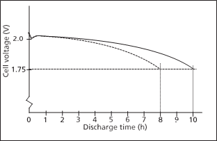 |
Figure 3 If the batteryreaches the end of dischargeat 80% (8 h) or before of the specified 10 h it isshall be replaced.
 |
Figure 4 Replacement of battery is recommended when thecapacity is 80% of rated.
it. Also less man-hour is needed for thetest. Contact your battery manufacturer for more information.
At higher rates it ismore important to supervise the battery’s temperature.
Between load tests, impedance measurement isan excellent tool for assessing the condition of batteries. Furthermore, itis recommended that an impedance test beperformed just prior to any load test to improve the correlation betweencapacity and impedance.
Impedance test
Impedance, an internalohmic test, is resistance in AC terms. With regard to DC battery systems,impedance indicates the condition of batteries. Since it teststhe condition of the entire electrical path of a battery fromterminal plate to terminal plate, impedance can find weaknesses in cells and intercellconnectors easily and reliably.
Basically, impedance test isdetermined byapplying anAC current signal, measuring theAC voltage drop across the cell or intercell connector and calculating the impedance
using Ohm’s Law. In practice, not only is the AC voltage drop measured but so is the AC current. The AC current is measuredbecause of other AC currents in a battery that are additive(subtractive). Other AC currents are present from the charger system. The test is performed by applying an AC test signal to the terminal plates. Then measure boththe total AC current
in the string and the voltage drop of each unit in the string bymeasuring each cell and intercell connectorconsecutively until the entire stringis measured. The impedance is calculated,displayed and stored. As the cells age, the internal impedanceincreases as depictedin figure 2. By measuringimpedance, the condition of each cell in the string can be measuredand trended to determine when to replace a cell or the string whichhelps in planning for budgetary needs.
The impedance test is a true four-wire, Kelvin-typemeasurement that providesexcellent reliability and highlyreproducible data on which to base sound decisions with regard to battery maintenance and replacement. Impedance is
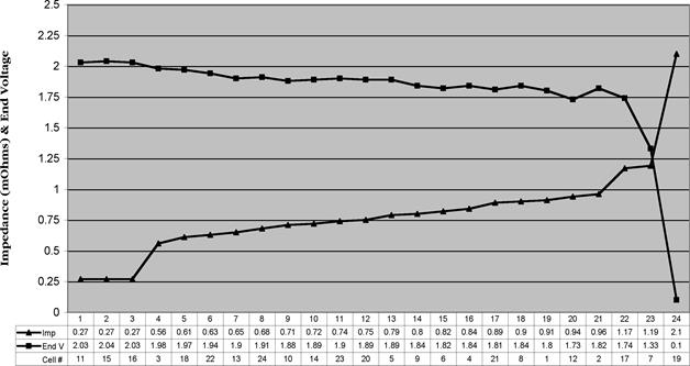
Figure 5 Ascending impedancewith corresponding end voltage
able tofind weak cells sothat proactive maintenance canbe performed. After all, the batteryis a cost but it is supporting a critical load or revenue stream.If a single cell goes openthen the entire string goes off line and the load is no longer supported. Therefore, it isimportant to find the weak cells before they cause a major failure.
The graph in figure 5 shows the effect of decreasing capacity on impedance. There is a strongcorrelation between impedance and capacity so that weak cells are ably and reliably found in sufficient time totake remedial action. The graph shows the reorganized impedancedata in ascending order with each cell’s corresponding load test end voltage.(Impedance in milliohms coincidentally is the same scale as the voltage, 0 to 2.5). This view, that is ascending impedance/descending voltage,groups the weak cells on the right side of thegraph to find them easily.
Impedance theory
A battery isnot simply resistive. There is also a capacitive term. After all, a battery is acapacitor, astorage device, and resistors cannot storeelectricity. figure 6 shows an electrical circuit, known as the Randles EquivalentCircuit, that depicts a batteryin simple terms. There are those who would have peoplebelieve that the capacitive term is not necessary and that the resistance is the only part that needs measuring.
Impedance measures both the DC resistance (the realcomponent in impedance) and the reactance (the imaginarycomponents in impedance). Only by measuring both can the capacitive term start to beunderstood. The other argument used against impedanceis that frequency is a variable in thereactance part of the impedance equation. That is true except that since Megger uses a fixed frequency, namely 50 or 60
Hz depending upon geography, it is alwaysthe same. This variable, w,now becomes a constant and, therefore, frequency does not affect the final result in any way. The only parts that affect the final resultare the partsthat vary withinthe battery, namely resistance and capacitance, whichpaint the whole capacity/condition picture.
In the diagram shown infigure 6,Rm isthe metallic resistance, Re is the electrolyte resistance, Rct is the charge transfer resistance, Wi is the Warburg impedanceand Cdl is the capacitance of the double layer. Rm includes all of the metallic
components one post to the other post, i.e., post, top lead andgrids and to a certain degree, the paste. Re is the resistance of theelectrolyte which doesn’t vary that much on a bulk basis.
But at the microscopic levelin the pores of the paste, it canbe significant. Rct is the resistance of the exchangeof ions from the acid to the paste.If the paste is sulphated, then Rct increasesor if that portion of the paste is not mechanically (electrically) attachedto the grid so that electrons cannot flowout of the cell. Warburgimpedance is essentially insignificantand is a function of the specificgravity. Cdl is what probably makes the most important contribution to battery capacity. By only measuringDC resistance, capacitance, animportant part
of the cell, is ignored. Impedance measures both DCresistance and capacitance.
A battery is complex and has more than one electrochemicalprocess occurring at any given time, e.g., ion diffusion, chargetransfer, etc. The capacity decreasesduring a dischargedue
to the conversion of active material and depletion of theacid. Also, as the plates sulphate, the resistance of the charge
transfer increases since thesulphate isless conductive than the active material. (See discussion about the differences between the thickness of the plates in long-duration versusshort- duration batteries.)
Intercell connection resistance
Intercell connection resistance isthe other half ofthe battery. A batteryis comprised of cells connected in a seriespath. If any one component failsthe entire seriesconnection fails.
Many times batteriesfail, not becauseof weak cells, but due toweak intercell connections, especially on lead posts which can cold-flow. Generally, hardwareshould be tightened to the low end of the torque scale that is recommended by thebattery manufacturer. But torque wrenches are a mechanicalmeans to verifylow electrical resistance. It is far better to actually perform an electrical testusing an appropriate instrument. It is a low electrical resistance that is desired. Thistest should be performedbefore the battery is commissioned.Proper intercell connections are necessary to ensure that discharge rates can be met. The instrument of choice is aDLRO® or a MOM which can easily verifythat all connections have been made properly.It can even find minor errors beforethe battery is commissioned, preventing possible causes of failure or damage to supportedequipment.
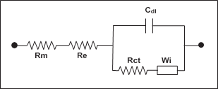
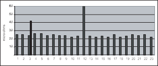
Figure 6 Randles equivalentcircuit Figure 7 Intercell connectionresistance bar graph
Testing intercell connection resistance performs two functions:
■ Validates intercell connection resistance
■ Finds possible gross errors with top lead internal to the cell
By following IEEE Recommended Practices, intercell connection resistance can bevalidated. Those recommended practices specify that the variation of intercellconnection resistance be less than 20%. This translates into 14 micro- ohms on a 70-micro-ohm intercell connection resistance.
This method can even find a washer stuck between the post and the intercell connector whereas torquingwill not. They also specify that 20% of the intercell connectors bemeasured quarterly and all intercellconnectors annually.
In multiple post batteries, it is possible to find thoserare gross errors in a cell’s top lead. (See multiplepost battery diagramin figure 1). On multiple-post cells, measure straightacross both connections, then measure diagonally to check for balancein the cell and connections. Measuring only straight across does not adequately test for either intercellconnection resistance or for gross top lead defects. This isdue to the parallel circuits for the current.
The graph in figure 7 shows the data obtainedfrom an actual 24-celltelephone (CO) batteryThe peak at connector#12 (cell 12 to 13) is an intertier cable
connection. Connector #3 was out of specification and itwas determined that one of the two bolts was not properly torqued. It was retorqued and retested. It came withinten percent of the string average after retorquing.
The negative plates(odd-numbered plates #1 through15)are all connected through negative top lead which isconnected to both negativeposts. Positive plates (even-
numbered) areconnected toeach other through positive top lead which is connected to both positiveposts. There are twointercell connectors betweenneg post 1 and pos post 1 and between neg post 2 and pos post 2.
The higher thecurrent draw the more critical isthe proper sizing of current-carrying components both internal to thecelland external. UPS batteries are usually designed for a highrate discharge lasting typically only 15-20 minutes. However, a telecommunications CO battery may haveonly a 500 Amp draw but can discharge for up to eight hours. So either combination can have disastrous effects due to improperly sized and maintained cells and intercellconnectors.
Testing and electrical paths
In order to properly test a multiple post cell, one mustunderstand its construction. Based on the diagram in figure 1, it can be seenthat there are two parallel paths for the test current to travel. If the test leads are placed on negpost 1 and pos post 1, the two parallelpaths are (1)
directly from neg post 1 to pos post 1 through their intercell
connectors and (2) neg post 1 down to the top lead,up to neg post 2 and across the intercell connectors to pos post 2down to the pos top lead and back up to pos post 1.The
two paths areparallel circuits and hence indistinguishable. If one bolt isloose, there isn’t anyway todetermine that since the test currentwill follow the path of least resistance. The better method to measure intercell connection resistance
is to measure diagonally from neg post 1 to pos post 2and again from neg post 2 to pos post 1. Compare the two readingsfor highest confidence. Admittedly, diagonal
measurements arestill parallel but thecomparison becomes more interesting due to the increased influenceof top lead and loose hardware.Diagonal measurements do not allow for a direct connection from post topost. In the case of
six-post cells, measure diagonally across thefarthest posts in both directions.
Voltage
Float voltage has traditionally been the mainstayof any testingprocedure. What is voltage? Voltage is the difference,electrically speaking, betweenthe lead and the lead oxideon the plates or between the nickel and the cadmium. The charger is the itemthat keeps them charged. The sum of
all of the cell voltagesmust be equal to the charger setting (except for cable losses.)This implies then that voltage merely indicates the state-of-charge (SOC) of the cells. There is no indication of a cell’sstate-of-health (SOH). A normalcell voltage doesn’t indicate anything except that the cell
is fully charged.An abnormal cell voltage, however,does tell you something about the condition of the cell. A low cellvoltage can indicate a shorted cell but only when the voltage finallydrops to about2.03. If a cell is low then othercells must be higher in voltage due to the charger setting.
Remember that the sum of all cell voltages must equal the chargersetting. Those cells that are higher are counteracting the low cell and generally speakingthe higher cells are
in better condition because they can tolerate the higher voltage.But those cells are being overcharged which over- heats them and accelerates grid corrosion and water losses.
Let’s say for the moment that the low voltage cell is notyet at 2.03, it is at 2.13 V. At 2.13 V it is not low enough to flag a concernbut it is degrading. It may or may not be
able to support the load when anoutage occurs. Impedance is able to find that weak cell sooner than voltage. Inthis case, impedance will decrease since it is an impending shortcircuit.
A similar examplecan be found in VRLA when it comes to dry-out or loss-of-compression.Voltage will not find this condition until it is far later in the battery’s life, until it is too late. Impedance finds this conditionmuch earlier so that remedial action can be performed.
So don’t confusefully charged with full capacity.
As said above, cell voltagedivergence can be caused by anumber of factors and one way to solve this problem could be to make an equalization charge. In an equalization charge procedure,the entire battery is charged at a higher (than normal) voltage for several hours to balancethe voltage in all
the cells. The procedure can lead to heating and possibly water loss. Itis recommended to follow the manufacturer’s procedureto avoid damaging the battery.
Specific gravity
Specific gravity is the measureof the sulphate in the acid of a lead-acid battery.It is also the measureof the potassium hydroxide electrolyte in nickel-cadmium battery but since the potassium hydroxideelectrolyte isn’t used in the chemicalreaction, it is not necessaryto measure it periodically.
Specific gravity traditionally has not providedmuch value in determining impending battery failure.In fact, it changes very little after the initial3 to 6 months of a battery’s life. This initial change is due to the completionof the formation process, which converts inactivepaste material into active materialby reacting with the sulphuric acid. A low specific gravity may meanthat the charger voltage is set too low causing plate sulphation to occur.
In a lead-acidbattery the sulphateis a closed system in thatthe sulphate must be either on the plates or in the acid. If thebattery is fully charged then the sulphatemust be in the acid. If the battery is discharged, the sulphate is on the plates. The end result is that specific gravityis a mirror image of voltageandthus state-of-charge. Specific gravity readings should be taken when things are amiss in the batteryto obtain as muchinformation about the battery as possible.
Different battery applications and geographies have varyingspecific gravities to accommodate rates,temperature, etc. Following is a table that describes someapplications and their specific gravities.
![]() Specific gravities and their applications
Specific gravities and their applications
Specific gravity |
Percent acid |
Application |
1.170 |
25 |
Tropical stationary |
1.215 |
30 |
Standard stationary |
1.250 |
35 |
UPS/high rate |
1.280 |
38 |
Automotive |
1.300 |
40 |
VRLA stationary |
1.320 |
42 |
Motive power |
1.400 |
50 |
Torpedo |
 Float current
Another leg of the Ohm’s Law triangleis current. The chargervoltage is used to keep a batterycharged but voltageis really the vehicle to getcurrent into the battery (or out of it during discharge). It is current that converts the lead sulphate back to activematerial on the grids.
There are two types of DC currenton a battery: rechargecurrent which is the current applied to recharge a battery after a dischargeand float current which is the current used tomaintain a battery in a fully charged state. If there is a difference betweenthe charger setting and the battery’s voltage, that difference will cause acurrent to flow. When the battery is fully charged [1], the only current flowing isthe float current which counteracts the self-discharge of the battery (<1%per week). Since the voltage differential
between the chargerand the battery is small,the float current is small. When there is a large voltage difference such as after a discharge the current is high and is limitedby the charger until the voltagedifference becomes less.When the current
is on the plateau in the graph below, this is calledcurrent limit. When the voltage differential becomes less, the chargecurrent is reduced as depicted on the downward sloping
charge current line on thegraph shown in figure 8. Thecharge voltage is the voltage of the battery, not the chargersetting which is why it is increasing.
Float current will vary with battery size. The larger the battery is, the more floatcurrent it will take to keep it fully charged.
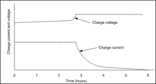 |
Figure 8 Constant-voltageConstant-current charge charac- teristics
[1] Cole, Bruce, et al., Operational Characteristics of VRLA Batteries Configured in Parallel Strings, GNB Technologies |
[2] Brown, AJ, An Innovative Digital Flat Current Measurement Technique - Part Two, Proceedings of BattConn® 2000 |
[3] Boisvert, Eric, Using Float Charging Current Measurements to Prevent Thermal Runaway on VRLA Batteries, Multitel |
[4] Ruhlmann, T., Monitoring of Valve Regulated Lead Acid Batteries, Proceedings of BattConn® 2000 |
Float current can increasefor a couple of reasons:ground faults on floatingbattery systems and internal batteryfaults. Ground faults are discussed later. As a battery’s internal impedance increases, it takesmore current to pass through that higher impedance. The increase in float current can be an indicatorof battery faults. In lieu of measuring float current, many of the sameconditions are found with impedance.
In VRLA batteries, float current[2,3] seems to be an indicator of battery problems, namely thermal runaway. Thermal runawayis the result of a battery problem,not the cause. Some of thecauses that can lead to thermal runawayare shorted cells, ground faults, dry-out, excessive charging and insufficient heat removal.This process takes anywhere from two weeks to four monthsto occur once the float current startsits increase. By measuringfloat current, it may be possible to avoid catastrophic failure of the battery and damage to connectedand nearby equipment. Impedance will find many of these same errors.
Ripple current
Batteries, as DC devices, preferto have only DC imposed on them. The charger’s job is toconvert AC into DC but no charger is 100% efficient. Frequently, filters are addedto chargers to remove the AC currentfrom the DC output.The AC current on the DC is called ripplecurrent. Batterymanufacturers have stated that more than about 5 A rmsof ripple for every 100 Ah of battery capacity can lead to
premature failure due to internalheating. Ripple voltageis not a concern since it isthe heating effect of the ripple current that damages batteries. The 5% ripple current figure is a roughestimate and dependsalso on the ambient temperature. Ripplecurrent can increase slowly as theelectronic components in the chargerage. Also if a diodegoes bad, the ripple currentcan increase more dramatically leading to heatingand premature death withoutanyone knowing it. Although impedance is not a measure of ripple current, ripple current is measured becauseof the way Megger designs its impedance instruments.
There is anecdotal evidence[4] that low frequency ripple (<10Hz) may charge and discharge a battery on a micro-scale.More research is necessary to prove this hypothesis. Excessivecycling can lead to prematuredeath of a battery regardless of the reasons for the cycling,be they outages, testing or maybemicro-cycling. One thing is true: the lower the AC is on the battery system,the less the damage is that can occur. VRLA batteries seem to be more sensitive to ripple currentthan their floodedcounterparts. It is then advisable to filter their chargersfor ripple current/voltage.
Temperature
It is well known that low temperatures slow up the internalchemical reactions in any battery;the degrees of reducedperformance vary according to thetechnology. For example, at temperatures around freezing, a VRLA may need capacitycompensation of 20%. The lead-calcium cell using 1.215
specific gravity acid will require adoubling ofcapacity, while the Ni-Cd willneed about 18% increased capacity.
At the other end of the temperature range, high temperature is the killer of all batteries. There will be no surpriseto find out that this impactvaries from one technology to another. Lead acid at 95˚F will experience a 50% shortenedlife, while Ni-Cd will have a 16-18% shortening oflife.
By applying what Arrhenius learned about chemical reactions, for every 18º F (10º C) increasein battery temperature, battery life is halved,battery life can start to be managed. The increased temperature causes faster positive gridcorrosion as well as otherfailure modes. By holding a lead-acid batteryat a temperature of 95º F (35º C) instead of the designed77º F (25º C), a 20-yearbattery will last only ten years, a ten-yearbattery only five years and so on. Increase the temperature byanother 18º F to 113º F (45º C), a 20-year battery will last only five years!
A battery is rarely held at a certain temperature for itsentire life. A more realistic scenariois for a battery to heat duringthe day and cool down at night with higher averagetemperatures in the summer and lower average temperatures in winter. It
is unfortunate but cooling the battery off to below 77º F(25º C) will not gain back the life that was lost. Once the positive grid corrodes,it cannot be converted back again. Furthermore,positive grid corrosion occurs at all temperatures, it is merely
a matter of speed of the corrosionrate. The end result is to control, as best as possible (back to cost versus risk), the temperatureof the batteries in the network.
IEEE 450, Annex H offers a method for calculating the impact of hightemperatures on a lead acid battery.
Data analysis
The essence ofany testing methodology ishow tointerpret the data to make some sense of it all. The same is true
of battery testing. If the data are to be hand-writtenand filed or if a printout from an instrument is reviewed then filed, then there is no usefulanalysis except if there is anemergency at that very moment.The real valuein battery testing lies in the trending of data to determine if problemsare imminent or a little farther out. Trending of battery data, especially impedance and capacity, is an excellent tool for budgetaryplanning. By watching the batteries degrade
over time, a decision can bemade asto when to replace a battery. With trending, emergencyreplacements decrease dramatically.
Like any other form ofmaintenance, battery testing and maintenance over the years has typically been recorded on some sort ofdata sheet. The data sheet waspossibly
reviewed andthen filed away, probably not reviewed again until a problem arose, if it could be found. With the use
of the PC, that same data which was filed away can beconverted to information which is useful and much easier to interpret. New data collectedcan be easily stored in digital format ratherthan on paper. It’s interesting to note that many maintenance programs still use paper with and without a PC. Still others are filling out the same old data sheets in digital format on the PCand then just filing it
electronically. Itseems almost the same as thepaper method just a different fillingcabinet. The key to makingdata useful
is the abilityto graph and manipulate the data. Do you think anyone in the stockmarket could make money if they did nothave all the charts and trends to view? Do you think we could put anything into orbit withoutplotting the orbit? Could you imagine looking at all the numbers associatedwith an orbit and try to make sense of it with out some sort of graphics?
This point isillustrated inFigure 9.
The data is not completedue to space limitations but it is theactual data of each sinusoid.It would be close to impossibleto see a difference between the two sets of data or the notching going on inthe bottom waveform when only the data is viewed, but without the data thewaveform could not be plotted. So now the question is what do we do withthe data from battery tests?To begin with whether the datais from one test or from severaltests on the same battery string the data should be trended.Now for some values like ambient temperature it will bedifficult to trend the data from one test becauseit is only one point.So let us review
what types of things could be plottedthat would make somesense with respect to batteries. Table below lists the types of measurements with respect to single testsor multiple tests from the same string.
When looking at data from a single test, the data isplotted against itself. Ideally when a string of batteries is installed they are installedat the same time and are all of the same vintage and should be somewhathomogenous. As the batteries age theymay all age the same but most likely there will be somecells which begin to fail early. In either case new or old we
are looking forthe differences. Below inthe table are strap

Figure 9 Waveform data vs. Waveformchart.
resistance measurements of a 60 cell string.It is easy enough to look through the data and see a few numberswhich do not seemcorrect, but when you look at the graph of the same data
it is a lot clearerwhat needs to be lookedat and what does not.
When looking at impedances whether from a single test ormultiple tests it is often advantageous to plot the percent deviation from average or the baseline.Figure 11 which showthe impedance plotted as percentdeviation of averageallows the user to quickly identify which cells are near limits whichhave been predetermined. In this example cells 1 and 3 which are both greater than ten percent above the average should be investigated further.You may also want to further investigate why the first sevencells are aboveaverage and the rest are not. Any time you have a grouping ofmeasurements which corresponds to the physical locationof the cells it shouldbe a cause for furtherinvestigation.
Single test of any string |
Multiple tests of same string |
Discharge |
Discharge |
Internal impedance |
Internal impedance |
Strap resistance |
Strap resistance |
Cell voltage |
Cell voltage |
Cell temperature |
Cell temperature |
Cell specific gravity |
Cell specific gravity |
|
Ambient temperature |
|
Charger output voltage |
|
Charger output current |
|
Ripple current |
|
Float current |
Battery measurements that can be plotted | |
 |
Inter-cell resistancemeasurements
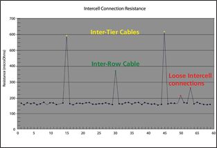
Figure 10 Inter-cell resistancegraph
Below are some suggestedpercentages to use as flags inimpedance testing. Over time, users will establish their own percentagedeviation warning values.
|
Percent variation from string average |
Percent variation from string average |
Percent deviation from baseline |
Percent deviation from baseline |
|
Warning |
Alarm |
Warning |
Alarm |
Lead-acid, Flooded |
15 |
30 |
30 |
50 |
Lead-acid, VRLA, AGM |
10 |
30 |
20 |
50 |
Lead-acid, VRLA, Gel |
20 |
30 |
30 |
50 |
NiCd, Flooded |
10 |
20 |
15 |
30 |
NiCd, Sealed |
10 |
20 |
15 |
30 |
Inter-cell Connections (Straps) |
15 |
20 |
|
|
Another method whichshould be used is trendingof historical data. For example, if you performtests every quarteron the same cells, then youwill want to chart the information with respect to time. Figure 12 shows the impedance measurementstrended for one cell which were taken every quarter.The first ten or eleven measurements seemed to be fine and then a steadyupward trend is very noticeable. This type of trend
in impedance should warrant further investigation as tothe cause. This method of trending over time can be used in all the datathat is measured.
All of thedata presented thus farhas been presented using a standard Excelspreadsheet. Spreadsheets are very usefuland have been around almost aslong ascomputers. There are software packages presently available such as PowerDB that automatically chart and trend the data for you. Theimportant step is to use graphics to help in the analysisof data that is newly measured and possibly with data still contained ina paper or electronic file.
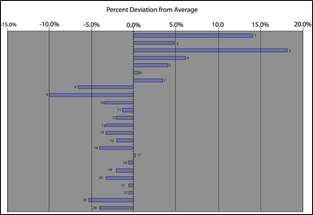

Figure 11 Impedance percentdeviation from average Figure 12 Single cell trending
Frequently asked questions
What does float voltageof a cell tell me?
Float voltage indicates that the charger is working, thatis,state-of-charge. It does not indicate the state-of-health
(condition) of the cell. It indicates that the cell is fullycharged, but don’t confusefully charged with full capacity.There have been many timesthat the float voltage is within acceptable limits and the battery fails. A lowfloat voltage may indicate that there is a short in the cell. This is evident by a float voltageat about 2.06 or below for lead-acid (if the charger is set for 2.17 Vper cell)
In some cases,a cell floats considerably higherthan the average. This may be caused by the high float voltagecell compensating for anothercell that is weak and is floatinglow. It is possiblethat one cell floats much higher to compensatefor several cells floating a little low. The total of all cells’ voltages mustequal the charger setting.
What are the recommended maintenance practices for the dif-ferent types of batteries?
IEEE Recommended (Maintenance) Practices cover the three main types of batteries: FloodedLead-acid (IEEE 450), Valve-Regulated Lead-acid (IEEE1188) and Nickel-Cadmium (IEEE 1106).Generally speaking, maintenance is essential to ensure adequateback-up time. There are differing levels ofmaintenance and varyingmaintenance intervals dependingupon the batterytype, site criticality and site conditions. For
example, ifa site has anelevated ambient temperature, then the batterieswill age more quickly implying more frequent maintenance visits and more frequent battery replacements.
How important is intercell connection resistance?
Our experience hasfound that many battery failures aredue to loose intercell connections that heat up and melt open ratherthan from cell failure. Whether a cell is weak or an intercell connectoris loose, one bad apple does spoil the whole bushel.
When lead acid batteries arefrequently cycled, the negative terminal may cold flow, thus looseningthe connection.
The proper sequenceof measuring multiplepost batteries is critical. Not all instruments providevalid intercell connection resistances due to their method of testing. Megger instrumentsprovide valid data.
What are some common failure modes?
 Failure mode depends upon the type of battery, the site conditions, application and other parameters.Please refer the summary on pages 7-8 or to the “Battery Failure Modes,”which can be found on the Meggerwebsite. Look underthe Battery Test Equipment product section. In the upperright- hand column under “Documents click for Application Guides,Articles and FAQs.
How often should impedancereadings be taken?
The frequency of impedance readingsvaries with battery type, site conditions andprevious maintenance practices. IEEE 1188 Recommended Practices suggests that a baseline shall be taken six months after battery has been in operation and then semi-annualquarterly. With that said, Megger recommends that VRLA batteries are measured quarterly due to their unpredictable natureand semi-annually for NiCd and floodedlead-acid. Impedance readingshould also be taken prior toevery capacity test.
At what point should I stop changingcells and replacethe entire battery?
In shorter strings(less than 40 cells/jars), the entire shouldbe replaced when three to five units have been replaced. In longerstrings, a similarpercentage that is replaced is the criterion.
How can I predict when I need to change a cell?
Even though there is not a perfect mathematicalcorrelation between battery capacity and impedance (or any other batterytest except a load test),the amount of increase in impedanceis a strong indicator of battery health.Megger has foundthat a 20 percentincrease in impedancefor flooded lead-acid generally correlates to 80% battery capacity. In VRLA, that increase is closer to 50% from the battery’s initial impedance orfrom the manufacturer’s baseline values.
Will capacitytesting destroy my battery?
The battery system is designedto provide back-uppower during all outagesthat appear during its lifetime.Performing a capacity test is nothingelse than simulating one outage but in a controlled way. Batteries can normally be deep discharged(discharged to manufacturer’s end-of discharge voltage)100
- 1000 times depending on type of battery. Using a few ofthese cycles has no real impact on the battery’s lifetime. On the other hand there is no reason to test more frequently than recommended by the standards.
Can I make a discharge test while my battery is still connectedto the load (on-line)?
Yes it is possible to do. Megger has test equipment that automatically senses and regulate the discharge current even when the batteries are connected to the ordinaryload. Most users chooseto make a 80% dischargetest when on-linein order to still have some backup time at the end of the test.
Megger productsoverview
Megger offers solutions toensure system performance with its comprehensive line of BatteryTest Equipment, Low Resistance Ohmmeters and Micro-ohmmeters, Insulation Testers, and Multimeters.
An overview of the variousproducts available is describedbelow. For more information on these and many other Megger products,visit our web site www.megger.com for the most
up-to-date news, product andservice information.
Impedance test equipment
Regardless of whetheryou are testing flooded lead-acid, VRLA or Ni-Cd cells,Megger has the right equipment for your battery maintenance requirements. The products and associated accessories provides meaningful data onbattery health without significant expense or any reduction in remainingbattery capacity.
Interruption in servicecan cause disasterto supported equipment and facilities. Consequently, adependable backup power system is critical so that when AC mains fail, costly service interruptions can be avoided. The battery impedancetest helps to identify weak cells beforethey cause problems.
Taking the batteryoff-line for testingis time consuming and adds risk to the process. This process isunnecessary with the on-line testing capabilities of the Megger familyof battery test products. The highlyrepeatable instruments help reduce downtime.
■ Determines the condition of lead-acid batteries
■  On-line testing with Pass/Warning/Fail calculations
■ Measures impedance, intercell connection resistance, cell voltage
■ Windows CE¨ Operating System with more than 16MB of memory
■ Measures float and ripplecurrents
The BITE3 is a compact,battery-operated, instrument with powerful on-board data analysistools. It is the first of its kindof instrument in that PowerDB can download all previous data to provide the best in on-site data analysis like no other instrument of its kind. The menus are easy to navigatewith
a bright, backlitLCD. The data display includesthe normal numeric arrangement but adds two graphical displays to help analyzeweak cells.
BITE2 andBITE2P
 |
■ Determines the condition of lead-acid and nickel-cadmiumbatteries up to 7000 Ah
■ On-board Pass/Warning/Fail indications
■ On-line testing
■ Robust, reliable instruments
■ Built-in printer (BITE2P)
The BITE2 and BITE2P Battery Impedance Test Equipmentwork by applying a test current across thebattery string while on- line, then measuringthe impedance, cell voltage and intercellconnection resistance. They also measureripple current which indicates the condition of the charger. Theinstruments help evaluate the conditionof the entire string from terminal plate to terminal plate and even thecharger.
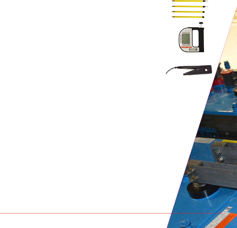 BITE® accessories
■ Enhances the capabilities of the BITE line
■ Full line of accessories
■ Designed for unique situations
■ Great for non-standard installations
Megger offers a complete line of accessories to enhance the capabilities of the BITE product line. There are extensioncables, calibration shunts,etc. Even though we have
many accessories, weare continually evaluating additional products asinterest arises.
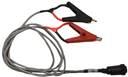
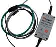 BITE3 Accessories
Kelvin Leads: Easily connect to terminal lugs. |
|
Flex CT: Measures escape current on parallel strings. NO NEED TO SEGMENT |
 Lighted Extension Probes: Ideal for those tight dark areas.
 Expanded Duplex Pistol Probes.Perfect for rooms with split battery strings. (6’between pistols)
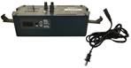 AC Power Supply.Operate your BITE3 off of an AC source.
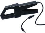 The Current Transformer kit for the BITE3 is formeasuring the current in noisybattery systems and to measure“escape
current” inparallel battery strings.
BITE2 andBITE2P Accessories
Bar Code Scanner: Scan your battery strings, no programming required. |
|
Flex CT: Measure ripple currents around large buss bars.
Extension Probes: Ideal for |
|
those tight areas.
Hydrometer: Measure specific gravity of flooded cells and import directly into your Power DB database. |
|
Mini CT: Measure ripple and test current in tight locations. |
 25
25
Capacity testing
TORKEL 900
■ Discharge testing for full insight into battery capacity
■ Enhanced safety featuresincluding spark free connection and emergency safety fuse
■ Ability to test the batterywithout disconnecting it fromthe system
■ High dischargecapacity shortens the test time
 |
■ A completestand-alone discharge test system
The TORKEL 900series isused toperform load/discharge testing which isthe only way todetermine battery system’s actual capacity. Together with the optional cell voltagelogger, BVM, connected directly to the TORKEL 900, it becomesa complete, stand-alone, discharge test system.
TORKEL comes in three models — 910, 930 and 950 — see table below.
The high discharge capacity ofTORKEL gives the opportunity to shortenthe test time. Discharging can take place at up to 220A, and if highercurrent is needed,two or more TORKEL units or extra load units, TXL, can be linked together.Tests can be conductedat constant current,constant power, constant resistance, or in accordance with a pre-selected load profile.
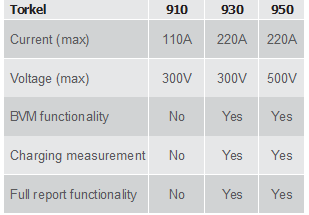 Testing can also be carried out without disconnecting the battery from the equipmentit serves. Via a dc clamp- on probe, TORKEL measuresthe total batterycurrent while regulating it at a constant level.Battery systems can be plusor minus grounded or free floating.
TORKEL Accessories
Torkel Viewer
Torkel viewer is asoftware used for test reporting. Theuser is able toedit andprint outtest reports. Tests aresaved toUSB stick on TORKEL and transferred to a PC.
Torkel viewer also includes calculation software that calculatesTORKEL/TXL configurations, orcalculates acurrent level for a certain TORKEL/TXL configuration.
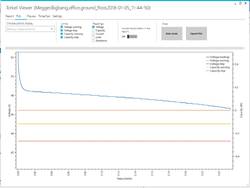 |
TXL830/850/865/870/890
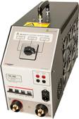 The TXL modelsare extra load unitsfor providing higher load currents. Together, TORKEL and the TXL extra loads form a system that can discharge batteries with currents up to kA.
Battery VoltageMeasurement (BVM)
The BVM isa battery cellblock voltage measurement system that isperformed on battery banks. It can be used in conjunction with a load device such as the TORKEL.
The BVM system is designed in modular form where one BVM unit is used foreach cell or block in the battery string to be tested. One BVM unit for each cellor block connects to the next in a daisy chain fashion.
The included dolphinclip can easily be removedand exchanged with different types of standard banana plug clamps and/or extensioncables to accommodate any batterconnection requirement.
 Up to 2 x 120 BVMs
can be daisy chained in a single battery bank under test.
Ground faulttracing equipment
There are two ground fault locating instruments from which to choose,the Battery Ground Fault Tracer (BGFT) and the BatteryGround-Fault Locator (BGL). The BGFT has superiornoise elimination while the BGL has an automatic bridgeto differentiate between high capacitance and low resistance. Here is a brief descriptionof each instrument.
Battery Ground Fault Tracer (BGFT)
■ Locates faultsup to 399K ohms
■ Easily locates ground faults in ungrounded DC battery systems
■ Operates in high electrical noise environment
■ Simplifies fault tracingby identifying faultcharacteristic (resistive and capacitive) magnitudes
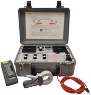 |
The Battery Ground-Fault Tracer is an economical, manually balanced instrument that identifies, tracks and locates groundfaults in ungrounded DC battery systems - on-line. It is particularly effective in high electrical noiseenvironments, as the strength of the test current can be adjusted up to80W.
The BGFT is particularly useful inany industry where supply of power for operatingmeasurement, communication and control equipment is critical.
The Battery Ground-Fault Tracer accelerates fault location by eliminatingtrial-and-error procedures and because faults can be located withoutgoing off-line. It is line operated and hasa manual bridge. The manualbridge is used to differentiate
between true, resistive faults and phantom, capacitive faults by using afeedback cable to null the capacitance. But themanual bridge is not required in order to trace faults.
The BGFT worksby converting line frequency to 20 Hz. Itthenpushes the AC signal through some coupling capacitorsto prevent transients on the DC buss and applies the ACsignal into the DC system while on-line. Using the hand-heldtracer, follow the signals with the highestreadings until the fault is found.
Battery Ground-fault Locator(BGL)
■ Ground faults in ungrounded DC battery systems are easilylocated
■ Features an automatic bridge
■ Battery operated
■ Simplifies fault tracingby identifying faultcharacteristic (resistive and capacitive) magnitudes
■ Locates faultsup to 100K ohms
The Battery Ground-Fault Locator was developedto detect, track and locateground faults on battery systems, without resorting to sectionalizing! The BGL tracks and locates groundfaults on live or dead battery systems.To save hours of unnecessary troubleshooting, the BGL readilydifferentiates between the resistive fault currents and capacitive charging currents. This feature allowsthe instrument to detect and track leakage paths, even in the presence of surge-suppressioncapacitors.
The BGL worksby filtering and applying an AC signalto the DC buss on-line. Thelow level output of the BGL allows it to bebattery-operated but is more sensitive to system noise.It has a built-in automatic bridge to differentiate between real (resistive) and phantom (capacitive) faults so only the real faultsare traced. The BGL is moved from panel to panel to continuethe tracing process until the fault is found. Since it has an automatic bridge it is very easy to trace faults and as such isbetter designed for the novice user.
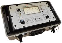 |
![]()
27
Digital Low Resistance Ohmmeters (DLRO) and Microhmmeters (MOM)
Many times batteries fail notbecause ofweak cells but dueto weak intercell connections. Torquing is amechanical method to ensurethat the electrical path resistances is very low. But
it does not truly indicate the quality of the electricalpath resistance. The only true method is to measure each intercellconnection resistance.
Megger has several DLROs and MOMs that areappropriate for intercell connection resistance. The portability ofthe instruments allows effortless mobility around battery strings.
The instruments arebuilt into strong, lightweight cases that are equally athome in the field or in the laboratory.
DLRO200
■ Small and weighs less than 15kg (33 lbs)
■ Test currents from 10A to 200 or 600 A DC
■ 0.1 μΩ best resolution
 Megger DLRO200 measures resistances between 0.1 µΩ and 1 Ω, at
high currents.This versatile instrument can provide testcurrents from 10 amps up to200 amps subject to the loadresistance and supply voltage. Alarge liquid crystal display provides all the information needed to perform atest.
DLRO 247000 series
■ Resolution to 0.1µΩ on
599.9 µΩ range
■ Standard inaccuracy of ±0.25%
■ Large, digital LED readout
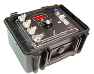 The 247000 Series of DLROs are afamily ofhighly accurate instruments that
provide asimple, practical and reliablemeans of making low-resistance tests in the field. They also areideal for production quality control. They operate on the four-wire measurementprinciple, thus eliminating lead and
contact resistances. With basic accuracies of ±0.25% and resolution down to 0.1 µΩ, they are nonetheless designed to berugged and portable for use at the job site.
DLRO10 and DLRO10X
■ 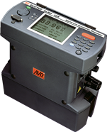 Accurate results in underthree seconds
■ Fuse protected to 600 V
■ Automatically detects continuity in potential and current connections
■ Alpha-numeric keypad for entering test notes (DLRO10X)
■ User configurable high and low limits (DLRO10X)
■ Printer output and memory(DLRO10X)
The DLRO10 and DLRO10X are fullyautomatic instruments, selecting the mostsuitable test current, up to 10 A DC to measure resistance from 0.1 µΩ to 2000 Ω on one of sevenranges.
 For users who desire more control over the measurement process, DLRO10Xuses a menu system to allow manual selection of the test current. DLRO10Xalso adds real-time download of results and on-board storagefor later download to a PC.
MOM200A and MOM600A
■ Resolution1µΩ on 1999 μΩ range
■ 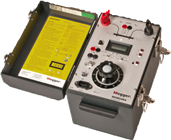 Standard inaccuracy of ±1%
MOM200A/600A are ideal for finding poor connections sincethey can put out 100 A for extended periods. Its range extending up to 20milliohms makes it ideal for measuring many differenttypes of connections.
 MOM690
■ Resolution 1µΩ on 200 mΩ range
■ Standard inaccuracy of ±1%
■ MOMWin™software
■ AC output
In addition to high current capacity, MOM690™ features
microprocessor-based measurement, storageand reporting. The built-insoftware enables you to carry out an individual test or an entire seriesof tests and store the results.
With the optional MOMWin™ software you can also export the test resultsto a PC for furtheranalysis and reporting.Ranges are set automatically, resistances are measuredcontinually and test results can be automaticallycaptured at a preset test current.
MOM2
■ Up to 220 A
■ Battery supplied
■ Lightweight – 1 kg
■ Auto range: 1 μΩ to 1000 mΩ
Its ruggedness and lightweight makes MOM2, a handheldinstrument, very suitablefor field work.The unit comes with a strong rubber holster accessory which makes it extra durable.
MOM2 is dimensioned to make a full day’s work of testing withoutrecharge. It can store 104 test values and transfer test datato a PC via Bluetooth.
The unit uses an ultracapacitor to generatethe high output current. The ultra capacitor is able to store a huge amount ofenergy compared to conventional capacitors and can deliververy high currentduring the dischargethanks to its very low internal resistance.
![]()
29
 Insulation Resistance Test Equipment
Batteries are supposedto be well insulated from adjacentequipment and metallic objects. The insulation provides severalbenefits: 1) keeps the charge in the battery rather than letting it leak, 2) provides for normalfloat current, and 3) reduces energy losses. If a battery is leaking electrolyte, then there may be a path to ground. When a path exists, the current needed tokeep the batteryfully charged increases. It also shortens
the length of back-up time of the battery depending upon the severity of the leak.An insulation resistance test can identify
whether there are leaks. The insulation resistance ismeasured across one of the terminals of the battery to someground,
presumably thebattery rack or tray. It isa very easy test to perform and providesfor a lot of confidence in the overall state of electrical insulation.
This test applies a DCvoltage, say500 Vdc, between thebuss, off-line and the rack. Then measures the DC leakagecurrent to calculate resistance in MΩ or GΩ. The higher the resistanceis the better. This test is recommended at installation and whenever a leak may be suspected (from tell-tale signs such as saltbuild-up.)
Megger offers the MIT400/2 Series insulation andcontinuity testers designed for electrical testing by powerutilities, industrials, telecommunication companies, commercial/ domestic electricians and anyone with unique test voltagerequirements. The wide range of features also makes the MIT400/2 Series ideal for maintenance technicians and engineers.
These instruments areavailable from as lowas 50V toas high as 1 kV. For analytical applications, multiple test voltagesare desired.
PowerDBTM
Acceptance& Maintenance Test Data Management Software
Test forms are designed for the majorityof the electrical apparatus on themarket today. PowerDB currently supports the following devices:
■ Batteries
■ Cables
■ Windows-based PC software available in three versions
■ Interfaces to instruments via either Serial RS232, USB port, Ethernet,or USBflash drive (depending on instrument)
■ Allows user to set up test routines in advance of testing
■ Allows analysis, comparison and trending of data
■ User can customize the User Interface (test form view) with theONBOARD and Full versions
PowerDB is a powerful software package providing data management for each of your acceptance andmaintenance
■ Circuit breakers
■ Coordination data
■ Disconnects
■ Generators
■ Groundfault tests
■ Ground Mat/Grid tests
■ Instrument transformers
■ Power transformers
■ Insulation fluids
■ Loadbreak switches
■ Motor control centers
■ Power factor tests
■ Relays
■ Switchboards
■ Transfer switches
■ Watthourmeters
■ Transducers
![]() testing jobs. Data can be imported from various sources, acquired directly from test instruments, or entered manually. Test results for all electricalapparatus are synchronized to your company’scentral database. Result and summary reports can beeasily generated.
testing jobs. Data can be imported from various sources, acquired directly from test instruments, or entered manually. Test results for all electricalapparatus are synchronized to your company’scentral database. Result and summary reports can beeasily generated.
PowerDBLite isfree software allowing youto usestandard PowerDB test forms with Megger instruments. It provides
a simple and consistent user interface to many Megger instrumentsincluding the BITE2, BITE3 and Torkel instruments.
PowerDB ONBOARD runs directly on the Megger test instrument, and the forms are the instrument’s user interface.Test results are transferred with a standard USB drive and can then be read into PowerDB or PowerDB Lite.
Test forms
Designed from a ground up approach, PowerDB utilizes over 200 industry standardtest forms that have been developedand used over 20 yearsby industry specialists.
Test data entry screens andprinted forms are identical allowing intuitive operation. What you see on the screen is whatis printed in the reports. Entire test documentation packages consisting of test reports,comment & deficiency summaries, table of contentsand field servicereports are created
with a single step. Once created, reports can bedelivered electronically via email, CD-ROM, web server or
Adobe® Acrobat®.
The software will perform extensive informationprocessing including equation calculations, temperature correction factorsand charting. Data trending for predictive failureanalysis is accomplished by charting historical results, stored in PowerDBor imported from other party’sproprietary database software, for any piece of equipment.
PowerDB provides a powerful editor to create or customize forms. No database knowledge is required. Simplydrag-and- drop tables, text boxes, images,charts, and more into a form.VBScript® can be used to definecalculations, use lookup tables, and even interfacewith other applications. Sections common to multiple forms, such as logos, headers and footers,can be defined once and included in many forms. Also, one change updatesall forms where it is used.
31
![]()
BATTERYTEST_AG_US_V04
The word 'Megger' is a registered trademark Copyright © 2017
2621 Van Buren Avenue • Norristown, PA 19403 USA 866-254-0962 • www.megger.com